A thermal bridge, also called a cold bridge or heat bridge, is an area or component of an object which has higher thermal conductivity than the surrounding materials, creating a path of least resistance for heat transfer. Thermal bridges result in an overall reduction in thermal resistance of the object. The term is frequently discussed in the context of a building’s thermal envelope where thermal bridges result in heat transfer into or out of conditioned space.
Thermal bridges in buildings may impact the amount of energy required to heat and cool a space, cause condensation (moisture) within the building envelope, and result in thermal discomfort.
There are strategies to reduce or prevent thermal bridging, such as limiting the amount of building members that span from unconditioned to conditioned space and applying continuous insulation materials to create thermal breaks.
Heat transfer occurs through three mechanisms: convection, radiation, and conduction. A thermal bridge is an example of heat transfer through conduction. The rate of heat transfer depends on the thermal conductivity of the material and the temperature difference experienced on either side of the thermal bridge. When a temperature difference is present, heat flow will follow the path of least resistance through the material with the highest thermal conductivity and lowest thermal resistance; this path is a thermal bridge.
Thermal bridging in construction
Frequently, thermal bridging is used in reference to a building’s thermal envelope, which is a layer of the building enclosure system that resists heat flow between the interior conditioned environment and the exterior unconditioned environment. Heat will transfer through a building’s thermal envelope at different rates depending on the materials present throughout the envelope. Heat transfer will be greater at thermal bridge locations than where insulation exists because there is less thermal resistance. In the winter, when exterior temperature is typically lower than interior temperature, heat flows outward, and will flow at greater rates through thermal bridges. At thermal bridge locations, the surface temperature on the inside of the building envelope will be lower than the surrounding area. In the summer, when the exterior temperature is typically higher than the interior temperature, heat flows inward, and at greater rates through thermal bridges. This causes winter heat losses and summer heat gains for conditioned spaces in buildings.
An assembly such as an exterior wall or insulated ceiling is generally classified by a U-factor, in W/m2·K, that reflects the overall rate of heat transfer per unit area for all the materials within an assembly, not just the insulation layer. Heat transfer via thermal bridges reduces the overall thermal resistance of an assembly, resulting in an increased U-factor.
Thermal bridges can occur at several locations within a building envelope; most commonly, they occur at junctions between two or more building elements.
Common locations include:
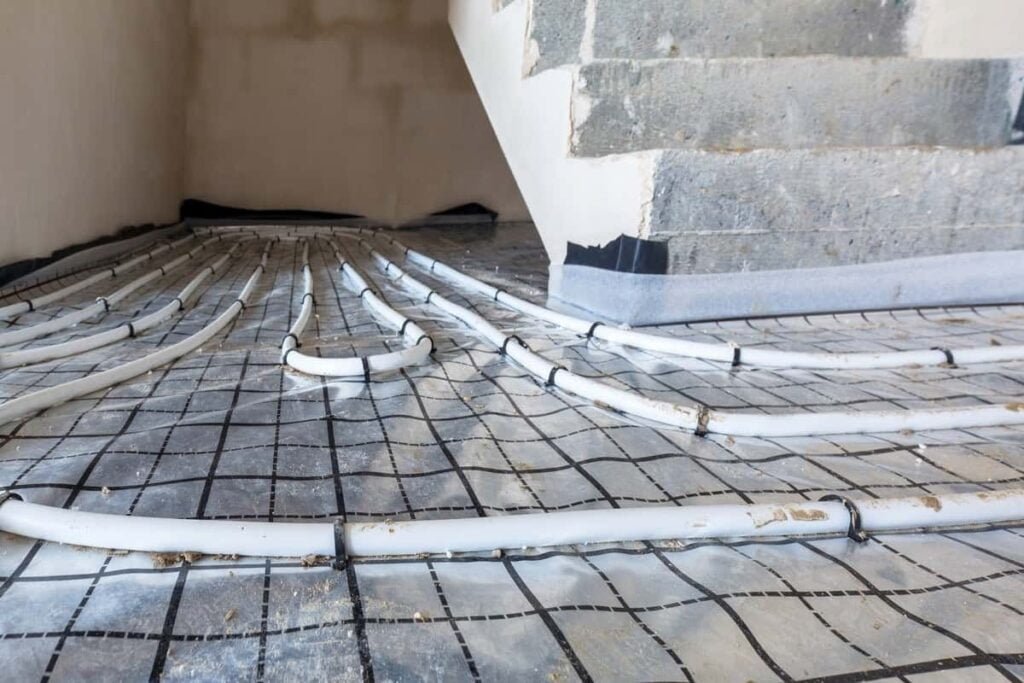
- Floor-to-wall or balcony-to-wall junctions, including slab-on-grade and concrete balconies or outdoor patios that extend the floor slab through the building envelope
- Roof/Ceiling-to-wall junctions, especially where full ceiling insulation depths may not be achieved
- Window-to-wall junctions
- Door-to-wall junctions
- Wall-to-wall junctions
- Wood, steel or concrete members, such as studs and joists, incorporated in exterior wall, ceiling, or roof construction
- Recessed luminaries that penetrate insulated ceilings
- Windows and doors, especially frames components
- Areas with gaps in or poorly installed insulation
- Metal ties in masonry cavity walls
- Masonry buildings
While thermal bridges exist in various types of building enclosures, masonry walls experience significantly increased U-factors caused by thermal bridges. Comparing thermal conductivities between different building materials allows for assessment of performance relative to other design options. Brick materials, which are usually used for facade enclosures, typically have higher thermal conductivities than timber, depending on the brick density and wood type. Concrete, which may be used for floors and edge beams in masonry buildings are common thermal bridges, especially at the corners. Depending on the physical makeup of the concrete, the thermal conductivity can be greater than that of brick materials. In addition to heat transfer, if the indoor environment is not adequately vented, thermal bridging may cause the brick material to absorb rainwater and humidity into the wall, which can result in mold growth and deterioration of building envelope material.
Curtain wall
Similar to masonry walls, curtain walls can experience significantly increases U-factors due to thermal bridging. Curtain wall frames are often constructed with highly conductive aluminum, which has a typical thermal conductivity above 200 W/m·K. In comparison, wood framing members are typically between 0.68 and 1.25 W/m·K. The aluminum frame for most curtain wall constructions extends from the exterior of the building through to the interior, creating thermal bridges.
Impacts of thermal bridging
Thermal bridging can result in increased energy required to heat or cool a conditioned space due to winter heat loss and summer heat gain. At interior locations near thermal bridges, occupants may experience thermal discomfort due to the difference in temperature. Additionally, when the temperature difference between indoor and outdoor space is large and there is warm and humid air indoors, such as the conditions experienced in the winter, there is a risk of condensation in the building envelope due to the cooler temperature on the interior surface at thermal bridge locations. Condensation can ultimately result in mold growth with consequent poor indoor air quality and insulation degradation, reducing the insulation performance and causing insulation to perform inconsistently throughout the thermal envelope
Strategies and methods to reduce thermal bridges in practical construction
There are several strategies that have been proven to reduce or eliminate thermal bridging depending on the cause, location, and the construction type. The objective of these strategies is to either create a thermal break where a building component would span from exterior to interior otherwise, or to reduce the number of building components spanning from exterior to interior.
These strategies include:
- A continuous thermal insulation layer in the thermal envelope, such as with rigid foam board insulation
- Lapping of insulation where direct continuity is not possible
- Double and staggered wall assemblies
- Structural Insulated Panels (SIPs) and Insulating Concrete Forms (ICFs)
- Reducing framing factor by eliminating unnecessary framing members, such as implemented with advanced framing
- Raised heel trusses at wall-to-roof junctions to increase insulation depth
- Quality insulation installation without voids or compressed insulation
- Installing double or triple pane windows with gas filler and low-emissivity coating
- Installing windows with thermally broken frames made of low conductivity material
Window-to-wall interfaces create additional challenges that need to be carefully reviewed for energy considerations and condensation risk due to positioning of the fenestration within the rest of the assembly.
Surface moisture due to condensation, typically occurring in such regions as floor-to-wall junctions and window installations, can be effectively prevented by means of multi-dimensional evaluation during planning and detail design.
Analysis methods and challenges
Due to their significant impacts on heat transfer, correctly modeling the impacts of thermal bridges is important to estimate overall energy use. Thermal bridges are characterized by multi-dimensional heat transfer, and therefore they cannot be adequately approximated by steady state one-dimensional (1D) models of calculation typically used to estimate the thermal performance of buildings in most building energy simulation tools. Steady state heat transfer models are based on simple heat flow where heat is driven by a temperature difference that does not fluctuate over time so that heat flow is always in one direction. This type of 1D model can substantially underestimate heat transfer through the envelope when thermal bridges are present, resulting in lower predicted building energy use.
The currently available solutions are to enable two-dimensional (2D) and three-dimensional (3D) heat transfer capabilities in modeling software or, more commonly, to use a method that translates multi-dimensional heat transfer into an equivalent 1D component to use in building simulation software. This latter method can be accomplished through the equivalent wall method in which a complex dynamic assembly, such as a wall with a thermal bridge, is represented by a 1D multi-layered assembly that has equivalent thermal characteristics.
(Written using Wikipaedia data & knowledge)